Difference between revisions of "Detectors"
(added photo from workshop) |
(Added biasing instructions) |
||
| (One intermediate revision by the same user not shown) | |||
| Line 1: | Line 1: | ||
=== Experiments using Neutron Detectors === | === Experiments using Neutron Detectors === | ||
| − | + | ;Boron Trifluoride | |
| − | [http://www.rtftechnologies.org/physics/neutron-detector.htm | + | : Here are some references on BF3 detectors |
| − | ] | + | * A commercial source with good information is [http://www.rtftechnologies.org/physics/fusor-mark3-neutron-detector.htm RTF Technologies] |
| − | + | * More design info on detectors-"picture and equations" [http://www.journalarchive.jst.go.jp/jnlpdf.php?cdjournal=jnst1964&cdvol=3&noissue=8&startpage=343&lang=en&from=jnlabstract 1964 Paper] | |
| − | More design info on detectors-"picture and equations" | + | * BF(3), Facts and Ionization Energy from [http://webbook.nist.gov/cgi/cbook.cgi?ID=C7637072&Mask=20#Ion-Energetics NIST] |
| − | [http://www.journalarchive.jst.go.jp/jnlpdf.php?cdjournal=jnst1964&cdvol=3&noissue=8&startpage=343&lang=en&from=jnlabstract] | + | * BF3 counter design info from Dr. Paul Frame of Oak Ridge National Lab [http://www.orau.org/ptp/collection/proportional%20counters/bf3info.htm ORAU Collection] |
| − | + | ||
| − | BF(3), Facts and Ionization Energy | + | |
| − | [http://webbook.nist.gov/cgi/cbook.cgi?ID=C7637072&Mask=20#Ion-Energetics] | + | |
| − | + | ||
| − | + | ||
| − | [http://www.orau.org/ptp/collection/proportional%20counters/bf3info.htm] | + | |
| Line 27: | Line 21: | ||
;Photomultiplier Tube | ;Photomultiplier Tube | ||
| − | : Tube | + | : Tube Base, Anode, dynode outs (these also have connections for Peltier Coolers [http://en.wikipedia.org/wiki/Thermoelectric_cooling Encyclopedia Reference] |
; NIM Bin | ; NIM Bin | ||
| Line 38: | Line 32: | ||
[[Image:NIMbinnai.png|thumb|450px|left | Drawing of NIM Electronics for 11C experiment]] | [[Image:NIMbinnai.png|thumb|450px|left | Drawing of NIM Electronics for 11C experiment]] | ||
[[Image:C11nimbin.jpg|thumb|450px|right| Actual NIM Electronics for 11C experiment with pulses]] | [[Image:C11nimbin.jpg|thumb|450px|right| Actual NIM Electronics for 11C experiment with pulses]] | ||
| + | |||
| + | |||
| + | === Biasing the NaI Detectors === | ||
| + | |||
| + | We will use two sodium iodide (NaI) detectors and a coincidence circuit to observe the decay of 11C. The NaI's are a pair of Bicron 2XMI 0.5/2H | ||
| + | which are 2" diameter, 2" tall cylindrical crystals with a Havar window and Bicron photomultiplier tube (PMT). The phototube bases were built in the Dept. of Physics and Astronomy Electronics Shop; they distribute the high voltage (negative!) to the PMT dynodes via a resistor chain. The tube base has connections for high voltage ("-HV"), dynode ("D", the seventh dynode) and anode ("A", the tenth and last dynode). | ||
| + | |||
| + | SAFETY NOTE: All surfaces on the detectors, electronics and cables are at ground potential. HV cables have grounded shields and all exposed HV is recessed away from stray fingers. Nevertheless, one should always follow the instructions carefully and be alert to frayed, damaged cables or loose connections. | ||
| + | |||
| + | ;Cabling | ||
| + | : 1. Check that the NIM Bin is off before making any high voltage connections. | ||
| + | : 2. Take a high voltage cable from the High Voltage (J1) connector on the rear of an Ortec 478 2kV power supply to the "-HV" input on an NaI tubebase. Note that high voltage cables are "RG-59" cable and have "SHV" connectors, which are not compatible with the signal connectors ("BNC"). | ||
| + | : 3. Take a signal cable from the tubebase anode "A" to the oscilloscope. This will be "tee-d" to a cable running to an input on the Philips Scientific Model 710 Discriminator. | ||
| + | : 4. Ensure that the HV power supplies are OFF (switch near the bottom of the front panel) and that they are set to Zero. | ||
| + | : 5. Power the Nim bin. Switch each HV supply ON. The front panel meter should display zero volts but the polarity light should indicate "Negative". | ||
| + | |||
| + | ;Setting the HIgh Voltage | ||
| + | Observe the two oscilloscope traces. Prepare the oscilloscope to see negative going pulses with amplitude of a few tens of milliVolts and rise time of tens of nanoSeconds. Put -500V on each detector and observe the result. Increase the voltage to a total of -1000V. You will see the pulses described above on the channel on which you have triggered. Switch the trigger to the other channel. Add -100 to -200 more volts to each detector. A higher voltage will increase the pulse size; it is desireable to have the detectors "gain matched". Voltages circa -1100V should be sufficient; requiring much higher voltage indicates that the crystal or crystal-PMT "coupling" is damaged. | ||
Latest revision as of 12:37, 30 September 2010
Experiments using Neutron Detectors
- Boron Trifluoride
- Here are some references on BF3 detectors
- A commercial source with good information is RTF Technologies
- More design info on detectors-"picture and equations" 1964 Paper
- BF(3), Facts and Ionization Energy from NIST
- BF3 counter design info from Dr. Paul Frame of Oak Ridge National Lab ORAU Collection
11C Identification and Measurement
- Sodium Iodide
- We use 2 2" Sodium Iodide detectors, manufacture by Bicron, now part of Saint-Gobain
These detectors have thin, havar windows because they were originally intended to measure light charged particles (proton, deuteron, triton, alpha) in light fusion reactions Paper from 1986
NaI was one of the first inorganic scintillators discovered (reference) and is still widely used for x-ray and gamma ray detection. It has good "stopping power" or long "radiation length", ie, good ability to stop photons. The energy resolution is poor compared to CsI or BaF2 and is not even in the same league as HPGe. However, it is better than most organic scintillators.
The NaI scintillates in the (blue/uv/don't remember) and so is coupled to a photomultiplier with a (don't know) window. The PMT acts to increase convert the scintillation light into electrons then multiply the electron current until it is large enough for us to amplify or observe.
- Photomultiplier Tube
- Tube Base, Anode, dynode outs (these also have connections for Peltier Coolers Encyclopedia Reference
- NIM Bin
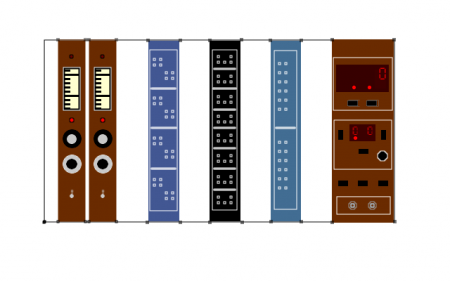
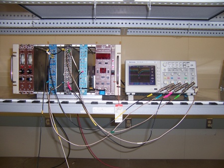
- A Nuclear Instrumentation Module (NIM) bin is a rack providing mechanical support and DC power to NIM modules. Similar devices were used as early as the 1950's but the NIM standard dates to 1968. For this experiment we will use the following NIM modules:
- HV Power supply for Tube Base, Ortec Model 478 Bias Supply, Bipolar, 0-2kV or similar
- Linear Fan In/Fan Out, LeCroy Model 428F
- Discriminator, Philips Scientific Model 710, Octal, leading edge discrimination of NIM negative signals
- Coincidence, LeCroy Research Systems Model 363AL 4-Fold Logic Gate
- Scalar, Ortec Model 871 Timer/Counter
Biasing the NaI Detectors
We will use two sodium iodide (NaI) detectors and a coincidence circuit to observe the decay of 11C. The NaI's are a pair of Bicron 2XMI 0.5/2H which are 2" diameter, 2" tall cylindrical crystals with a Havar window and Bicron photomultiplier tube (PMT). The phototube bases were built in the Dept. of Physics and Astronomy Electronics Shop; they distribute the high voltage (negative!) to the PMT dynodes via a resistor chain. The tube base has connections for high voltage ("-HV"), dynode ("D", the seventh dynode) and anode ("A", the tenth and last dynode).
SAFETY NOTE: All surfaces on the detectors, electronics and cables are at ground potential. HV cables have grounded shields and all exposed HV is recessed away from stray fingers. Nevertheless, one should always follow the instructions carefully and be alert to frayed, damaged cables or loose connections.
- Cabling
- 1. Check that the NIM Bin is off before making any high voltage connections.
- 2. Take a high voltage cable from the High Voltage (J1) connector on the rear of an Ortec 478 2kV power supply to the "-HV" input on an NaI tubebase. Note that high voltage cables are "RG-59" cable and have "SHV" connectors, which are not compatible with the signal connectors ("BNC").
- 3. Take a signal cable from the tubebase anode "A" to the oscilloscope. This will be "tee-d" to a cable running to an input on the Philips Scientific Model 710 Discriminator.
- 4. Ensure that the HV power supplies are OFF (switch near the bottom of the front panel) and that they are set to Zero.
- 5. Power the Nim bin. Switch each HV supply ON. The front panel meter should display zero volts but the polarity light should indicate "Negative".
- Setting the HIgh Voltage
Observe the two oscilloscope traces. Prepare the oscilloscope to see negative going pulses with amplitude of a few tens of milliVolts and rise time of tens of nanoSeconds. Put -500V on each detector and observe the result. Increase the voltage to a total of -1000V. You will see the pulses described above on the channel on which you have triggered. Switch the trigger to the other channel. Add -100 to -200 more volts to each detector. A higher voltage will increase the pulse size; it is desireable to have the detectors "gain matched". Voltages circa -1100V should be sufficient; requiring much higher voltage indicates that the crystal or crystal-PMT "coupling" is damaged.

